


يُعد اختيار حلول التشكيل الأكثر فعالية أثناء تنفيذ أعمال التشغيل الدقيق أمرًا بالغ الأهمية من حيث الأداء وجودة النتائج. تُخصص المقالة التالية لفوائد قواطع النهايات الحلزونية المتغيرة. دعونا نُركز بشكل خاص على تطوير تصميمات فلوت هذه الأدوات. سيُتيح لنا تحليل أدوات القطع هذه الكشف عن كيفية مساهمة التصميم الهندسي المُحدد لهذه الأدوات في تحسين الاستقرار، وتقليل الاهتزاز، وتحسين طرق إخراج الرقائق. يُمكّن الشرح الفني المُقدم هنا المهندسين والميكانيكيين من زيادة الكفاءة والإنتاجية في عمليات التشغيل.
ما الذي تقوم به مطحنة النهاية الحلزونية المتغيرة على وجه التحديد؟

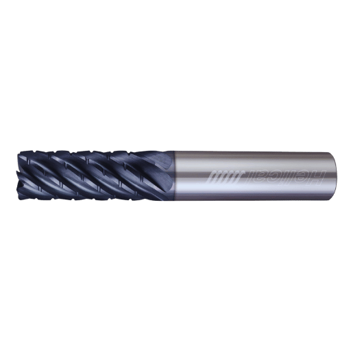
وظيفة قاطعة النهاية الحلزونية المتغيرة
تتميز قواطع النهايات الحلزونية المتغيرة بتصميم أحادي التجويف لحافة القطع، يمتد للخارج ويتغير مع زاوية الحلزون. هذه التناقضات تُضعف التوافقيات أثناء عمليات التصنيعمما يُسهّل مهام القطع التي تتطلب استخدام أدوات أحادية الطرف بكفاءة أعلى. كما يُساعد هذا التكوين غير المتساوي على تحسين إخراج الرقائق من خلال منع تكدسها، وبالتالي تحسين معدل إزالة المواد. كما يُطيل عمر الأدوات بتقليل القوى المُطبقة على مناطق مُحددة من أداة القطع، حيث تؤدي هذه المناطق وظيفة القطع نفسها. إجمالاً، يُحسّن تكوين الحلزون المتغير أداء القطع ودقته بشكل فعال في عمليات التشغيل المختلفة.
إيجابيات وسلبيات قواطع نهاية الحلزون المتغير
يتوفر تشوه الشكل بأبعاد مختلفة، وعادةً ما تتكون حافتا القطع الرصاصيتان الأخريان من خصائص مختلفة لقواطع النهايات الحلزونية المتغيرة، مما يمنحها إمكانيات تطبيقية أوسع. أولًا، عند العمل بمواد تشغيل معقدة، يزيد هذا من أداء عملية التشغيل. أولًا، ينخفض مستوى الاهتزازات التوافقية بشكل ملحوظ. وبالتالي، يصبح سطح القطعة المُشَغَّلة أفضل، ويقل احتمال حدوث عيوب. إنه شكل... مطحنة نهاية يسمح هذا بتنظيف الرقائق بشكل صحيح ويمنع ارتفاع درجة حرارة الأداة. إضافةً إلى ذلك، يُؤدي تغيير زاوية الحلزون المحوري إلى توازن القوى الخلفية، مما يُقلل من تلامس الأداة مع العمل، ويزيد من دقة الأبعاد. يتم تحقيق إنتاجية أعلى للنشاط بأكمله، وخفض أوقات الدورات، وما إلى ذلك، في عمليات التشغيل الدقيقة. وبفضل هذه الميزة المذكورة أعلاه، تُستخدم هذه الأدوات مع مواد قطع العمل المختلفة.
مجالات تطبيق قواطع النهاية ذات الزاوية المتغيرة
بفضل كفاءتها ودقتها، تُستخدم قواطع النهايات الحلزونية المتغيرة في تصنيع قطع الغيار في صناعات الطيران والسيارات والقطاع الطبي. ففي مجال الطيران، تُمكّن هذه القواطع من تصنيع مكونات ذات أشكال معقدة من مواد خفيفة الوزن، بما في ذلك التيتانيوم وسبائكه. ويستخدم قطاع السيارات هذه القواطع. مطاحن نهاية أثناء التصنيع لمكونات المحرك، فهي أسرع مع ضمان تشطيب سطحي جيد ودقة أبعاد. تُستخدم هذه القواطع الحلزونية المتغيرة أيضًا في تصنيع الأدوات الجراحية عالية الجودة في المجال الطبي، حيث تُعدّ الدقة والموثوقية بالغتي الأهمية. علاوة على ذلك، تُستخدم أيضًا في تصنيع القوالب والقوالب، حيث يُحسّن زمن الدورة أضعافًا مضاعفة ويُقلل التآكل في التطبيقات عالية السرعة.
ما هي العلاقة بين زاوية الحلزون وأداء الطحن؟
لماذا يعتبر Helix Hayes مهمًا؟
زوايا الحلزون هي سمات تصميمية لقواطع النهايات، ولها دور مهم في التأثير على عوامل مثل اهتزاز الأداة وكفاءة القطع. من ناحية أخرى، إذا كانت زاوية الحلزون منخفضة، فستكون قوى القطع كبيرة، وسيكون هناك خلوص فعال للرقائق، وهو مناسب للمواد الصلبة. من ناحية أخرى، تقلل زاوية الحلزون الكبيرة قوى القطع المحورية مع زيادة حركة القطع، وهو مناسب للمواد الأكثر ليونة، بالإضافة إلى تحقيق جودة سطح أفضل باستخدام قواطع النهايات الحلزونية. بهذه الطريقة، يتمكن المصنعون من تحسين فعالية أدوات القطع في مهام معينة من خلال اختيار زاوية الحلزون الدقيقة، مما يوفر في النهاية جودة أفضل ومقاومة للتآكل ويقلل من تسرب وقت توقف التشغيل.
التمييز بين قواطع نهاية الحلزون العالي والقواطع النهائية الحلزونية القياسية
تتميز قواطع النهايات الحلزونية العالية بزوايا حلزونية تتراوح بين المتوسطة والشديدة، وتتراوح بين 45 و60 درجة تقريبًا، مما يجعل عملية القطع أكثر كفاءة من قواطع النهايات الحلزونية القياسية، ويسمح بإزالة الرقائق بشكل أفضل. تُعد هذه استراتيجية جيدة للمواد اللينة فيما يتعلق بالسمات الجمالية التي يتم استهدافها. على العكس من ذلك، تُظهر قواطع النهايات القياسية حلزونات بزوايا تتراوح بين 30 و35 درجة، وهي أكثر تدميرًا، مما يتيح قطع المواد الأكثر صلابة. المتغيرات في هذه الحالة هي قواطع النهايات الحلزونية العالية والقياسية. فبينما تسمح التصميمات الهجينة العالية بزيادة السرعات والتلميع، توفر التصميمات القياسية ثباتًا تقليديًا بخصائص متينة تعمل في التطبيقات العدوانية. يُعد النوع الصحيح مهمًا لأنه يؤثر على دقة التشغيل بالنسبة لطبيعة المنتج النهائي والخيارات القائمة على كيفية استخدام المواد.
كيفية اختيار زاوية الحلزون الصحيحة
أهم هذه العوامل هو الاختيار الصحيح لزاوية الحلزون وفقًا لنوع المادة: بالنسبة للمواد الأكثر صلابة، تكون زاوية الحلزون القياسية من 30 إلى 35 درجة مناسبة بحيث يكون هناك استقرار وتوزيع مناسب للقوى. لذلك، يجب اختيار زاوية حلزون عالية (حوالي 45 إلى 60) في المواد اللينة التي تتطلب تشطيبًا سطحيًا ناعمًا للغاية لإزالة الرقائق بسهولة وتحسين تشطيب السطح. بالإضافة إلى ذلك، من المهم مراعاة المعلمات الوظيفية للجزء المراد تشكيله، على سبيل المثال، سرعة التصنيع والجودة المطلوبة للتصنيع؛ تسمح زوايا الحلزون العالية بمزيد من السرعات والعمل التجميلي، وتتحمل الزوايا القياسية الأحمال بشكل أفضل في ظروف العمل المكثفة. عند قطع المواد، تشير سرعة التشغيل الفعالة لهندسة الجزء النهائي، بناءً على خصائص المادة وظروف التشغيل، إلى وجود زاوية حلزون مريحة ومثالية لكل مادة.
ما هي السمات الرئيسية لمطاحن نهاية كربيد؟

التركيب المادي لقواطع الكربيد الطرفية
تتكون قواطع الكربيد الطرفية بشكل أساسي من كربيد التنغستن، وهي مادة متينة شديدة التحمل تتميز بمقاومة عالية للتآكل وكفاءة قطع عالية. يتيح هذا التركيب إنتاج أدوات تفقد جودتها الفائقة حتى مع الاستخدام لفترات طويلة، وخاصةً قواطع الكربيد الطرفية الحلزونية المصممة لسبائك الألومنيوم ذات الأداء الأمثل. علاوة على ذلك، يمكن استخدام الكوبالت كمادة رابطة في قواطع الكربيد الطرفية لتحسين متانة الأداة واستقرارها الحراري. طُوّرت هذه المواد خصيصًا لأغراضها الخاصة، بهدف تعزيز أداء وسلامة قواطع الكربيد الطرفية أثناء الاستخدام، وخاصةً في تشغيل النحاس عالي السرعة.
لماذا يعتبر الكربيد أفضل مقارنة بالبدائل الأخرى المتاحة؟
هناك مزايا لاستخدام قواطع الكربيد الطرفية مقارنةً بالمواد القائمة على الفولاذ عالي السرعة (HSS) والكوبالت. أولًا، يتميز الكربيد بصلابة أعلى من هذه المواد، مما يسمح بالاحتفاظ بشكل أفضل بالهندسة الحادة لأدوات القطع وسرعات قطع أعلى في قواطع الكربيد الطرفية الحلزونية. ثانيًا، تقلل صلابة الكربيد العالية من تآكل الأدوات وتساعد على زيادة فعاليتها من حيث التكلفة مع مرور الوقت من خلال زيادة عمرها الافتراضي وتقليل تكاليف الصيانة. بالإضافة إلى ذلك، يُحسّن تأثير الكربيد في درجات الحرارة العالية من أدائه في ظروف التشغيل الأكثر صعوبة. وأخيرًا، يُحسّن أداء أدوات الكربيد، الذي يظل ثابتًا نسبيًا بغض النظر عن ظروف التشغيل، من جودة المنتج النهائي وتشطيبه النهائي عند تشغيل المواد المعقدة.
كيفية اختيار القاطع النهائي بناءً على متطلبات الألومنيوم وسبائكه؟

ميزات تصميم الطاحونة النهائية المستخدمة في سبائك الألومنيوم
عند البحث عن وصلات لقواطع طرفية للألمنيوم وسبائكه، يجب مراعاة خصائص مثل تصميم المخروط، والطلاء، والهندسة، وخاصةً في قواطع طرفية لسبائك الألومنيوم. كما تُسهّل زاوية الحلزون العالية (حوالي 45 درجة) إزالة الرقائق وتقلل من احتمالية تكدسها. تضمن الأدوات ذات عدد أقل من المخروطات (عادةً اثنين أو ثلاثة) إزالة الرقائق، مما يُحسّن عمليات التشغيل. بعض الطلاءات، مثل TiN أو TiAlN، تُحسّن خصائص مقاومة الاحتكاك للأداة وتُعطيها مقاومة للتآكل. لتحسين جودة قطع الألومنيوم المُشَكَّلة، يُنصح باستخدام أدوات قطع ذات حواف حادة لتحقيق تشطيبات دقيقة ودقة أبعاد.
أهمية تصميم نصف قطر الزاوية وأداة الفلوت
يُعدّ نصف قطر زاوية قاطعة القطع الطرفية عاملاً أساسياً في الأداء العام للأداة في تشغيل الألومنيوم. فكبر نصف قطر الزاوية يُعزز متانة الأداة، ويُقلل من آثار التقطيع أثناء التشغيل، ويُحسّن تشطيبات السطح. إضافةً إلى ذلك، يُحافظ تصميم المخروط على أهميته في تخفيف تفريغ الرقاقة ومسار سائل التبريد. يُتيح التصميم المخروطي بعدد مُحدد مُسبقاً من القنوات خلوصاً مناسباً للرقاقة، مما يمنع تدفقها إلى الأداة، مما يُسبب تآكلها وأخطاء أبعادها. تُعدّ أنصاف أقطار وخراطيم النحاس مهمةً للغاية في عمليات القطع لتحسين ظروف التشغيل على قطعة العمل.
نصائح Guhring وMA Ford® TuffCut®
اقترح جورينج أنه عند تشغيل الألومنيوم وسبائكه، يُنصح باستخدام قواطع طرفية ذات زوايا حلزونية عالية وعدة أخاديد تساوي اثنين أو أكثر لضمان إزالة الرقائق بشكل صحيح. كما يُوصي بتطبيق طلاء TiAlN لزيادة عمر الأداة. تُشدد شركة MA Ford® TuffCut® على تطوير زاوية مستديرة للأداة مع لمسة نهائية أفضل من الحواف النظيفة، وذلك في ظل الحاجة إلى تصميمات لإزالة الرقائق من الأدوات الحلزونية. ويدعو جميع هؤلاء المصنّعين إلى إجراء تقييم دوري لمدى تآكل أداة القطع للحفاظ على سلامة عمليات التشغيل.
ما هي المعلمات التشغيلية لتحسين عمر الأداة؟
معلمات التشغيل الصحيحة
لتحقيق أقصى عمر افتراضي للأداة في تشغيل الألومنيوم، يجب أن تتوافق معلمات التشغيل التي سيتم وضعها مع الخصائص الوظيفية للأداة والمادة التي يتم العمل عليها. تتضمن هذه المعلمات سرعات القطع ومعدلات التغذية وعمق القطع، خاصةً عند استخدامها أثناء عمليات الطحن الطرفي. في حين أنه لا توجد وثائق نهائية حول هذا الأمر، يُنصح بضبط سرعة القطع من 500 إلى 1000 قدم مكعب في الدقيقة لمعظم سبائك الألومنيوم. وبالمثل، يجب أن تلبي التغذية التشغيلية أو الطولية المواصفات الموصى بها لقاطع الطحن الطرفي مع قيم طبيعية تتراوح بين 0.003 و0.015 بوصة لكل سن. فيما يتعلق بأدوات القطع، يلزم أيضًا عمق القطع، والذي لا يعتمد فقط على قطر الأداة ولكن أيضًا على طبيعة العمل، والذي يتراوح عادةً من 0.010 إلى 0.100 بوصة. تتطلب هذه المعلمات التحسين المناسب في الأداء لأنها تساعد في الدقة في التشغيل وتقليل تآكل الأدوات.
تأثير الاهتزازات التوافقية على عمر الأداة
يمكن أن تُسبب الاهتزازات التوافقية انخفاضًا كبيرًا في عمر الأدوات، إذ تزيد من إجهاد القاطع وتآكل حواف القطع. قد تُسبب هذه الاهتزازات قطعًا خاطئًا أو ظروف قطع مفرطة، مما يؤدي إلى عدم انتظام قوى القطع، مما يُقلل من عمر الأدوات، وخاصةً أثناء عمليات التفريز الطرفي. علاوة على ذلك، قد تُؤدي هذه الاهتزازات أيضًا إلى تدهور جودة تشطيب السطح وتسبب أخطاء في دقة تشغيل قطع العمل. لذلك، ينبغي اتخاذ التدابير المناسبة المتعلقة بتطبيق أساليب فعالة لتخميد الاهتزازات والتحكم في حالات المغزل للحد من هذه التأثيرات والحفاظ على كفاءة عمل الأدوات.
تعظيم معدلات الإزالة للطحن عالي الكفاءة
إذا كان الهدف هو تحسين معدلات الإزالة في عمليات الطحن عالية الكفاءة، فمن الضروري للغاية القيام بذلك دون المساس بالاستقرار من خلال تعديل معايير القطع بشكل مناسب. هذا يعني استخدام سرعة قطع عالية جدًا، تتراوح عادةً بين 800 و1200 قدم مكعب في الدقيقة، عند قطع الألومنيوم بمعدل تغذية عالٍ جدًا يتوافق مع أداة تتراوح بين 0.015 و0.025 بوصة لكل سن. يجب زيادة القطع بناءً على حدود الأداة، والتي غالبًا ما تتراوح بين 0.100 و0.250 بوصة، وهو أمر أكثر أهمية للقطع العميق لإزالة المزيد من المواد. بفضل أداة متينة وظروف تبريد جيدة، يمكن تصنيع قطع عالية الجودة، حتى مع معدلات إزالة عالية للمواد.
كيفية التحكم في الثرثرة أثناء الطحن؟

الثرثرة في مطاحن Helix End Mills
يحدث طحن السطح النهائي عند الضغط لأسفل عن طريق الانزلاق والقطع مع القاطع الدوار في النهاية. يؤدي معدل طحن السطح المرتفع، عند محاولة استخدام آلات بسيطة، في أغلب الأحيان إلى عدم استقرار في التشغيل. يتضمن ذلك هذا الانحراف الذي قد يزداد من خلال أنواع القطع أو من خلال القوى المطبقة. علاوة على ذلك، فإن عوامل أخرى، مثل ميزات تصميم الأدوات، مثل زاوية الحلزون العالية أو الخلوص المنخفض، تخلق أيضًا فرصًا للاهتزاز. تتمتع المواد المختلفة بقدرات مختلفة على القطع، وغالبًا ما لا يتم تثبيت قطع العمل بشكل مكثف، مما يؤدي إلى سوء التوجيه. يكون الاهتزاز صعبًا لأن الصناعة تقطع بشكل أعمق وأعمق بينما تُترك الأدوات كما هي. ولكن لتجنب هذا التأثير، من الأهمية بمكان اختيار الأداة الصحيحة واستخدام نسب دوران عالية الأداء للمغزل، مما يوفر عددًا كافيًا من المشابك لتعزيز الاستقرار.
تقنيات تقليل التحكم في الثرثرة
- زيادة صلابة الأداة: استخدم أدوات قطع أقصر واستخدم منصات تصنيع صلبة للغاية لزيادة القوة وتقليل فرص ثني الأدوات.
- تحسين معلمات القطع:تغيير دورات المغزل المخصصة أو سرعات القطع من أجل تقليل الاضطراب وتحقيق قطع ناجح.
- زيادة التخميد: استخدم أو وفر الأدوات التي ستستخدم أجهزة أو نقاط امتصاص الصدمات.
- حدد أداة الهندسة المناسبة: استخدم الأدوات المناسبة مع زاوية الحلزون الصحيحة والمساحة المناسبة لتقليل فرص الحوار.
- تعزيز تثبيت العمل: استخدم تركيبات وأدوات تثبيت أكثر قوة أو حاملات عمل ومشابك لقطعة العمل عند التصنيع.
- تنفيذ تحسين مسار الأداة: اعتماد استراتيجيات المشاركة المستمرة واستخدام مسارات الأدوات التكيفية لتقليل التغييرات المفاجئة في الحمل.
- قم بإجراء فحوصات الأدوات والصيانة بشكل روتيني: حافظ على الأدوات في حالة قطع مناسبة عن طريق شحذها وتقليل التآكل عليها عند الثرثرة.
إعدادات الماكينة واعتبارات قطعة العمل
من الضروري التحكم في إعدادات الآلة وظروف قطعة العمل للحد من الاهتزاز أثناء التشغيل. في البداية، يجب ضبط سرعة المغزل بدقة؛ فعلى سبيل المثال، إذا كانت عالية جدًا، فقد يحدث تشوه، وإذا كانت منخفضة جدًا، فقد لا تكون جودة القطع مرضية. يؤثر معدل تغذية القطع بشكل كبير على تكوين الرقاقة. لذلك، يُنصح باستخدام القيمة الدائمة والمتوسطة عند الضرورة لتقليل الاهتزاز. بالإضافة إلى ذلك، يجب اتباع مسار الأداة وهيكلها لتجنب حدوث تغييرات مفاجئة في الحمل.
عند تحليل قطعة العمل المذكورة أعلاه، من المهم ملاحظة وتقييم خصائصها الهيكلية، إذ قد تختلف أنواع القطع، مثل القطع الحلزوني. باستخدام تركيبات مناسبة تُحدد موضع قطعة العمل بدقة، يتم تجنب الحركة الدورانية المُسببة للاهتزازات. وأخيرًا، يجب أيضًا تقييم معلمات الآلة، بما في ذلك مستوى المحاذاة، والصلابة، وغياب القطع والخدوش والأضرار، لأن هذه المعلمات تؤثر بشكل مباشر على استقرار القاعدة وكفاءة عمليات القطع.
المصادر المرجعية
الأسئلة المتداولة (الأسئلة الشائعة)
س: ما هي مزايا قواطع النهاية الحلزونية المتغيرة؟
ج: توفر قواطع الطحن الحلزونية المتغيرة مزايا عديدة، مثل انخفاض الاهتزاز، وتحسين إزالة الرقائق، وارتفاع معدلات التغذية. ...
س: ما هو تأثير زاوية حلزون المطحنة النهائية على الأداء؟
ج: زاوية حلزون الطحن الطرفي عامل مهم يؤثر على أداء الأداة. في معظم الحالات، يكون الحلزون الأكبر حجمًا...
س: ما هي بعض منتجات الطحن الحلزوني المتغير المستخدمة على نطاق واسع والمتوفرة في السوق؟
ج: تتضمن بعض منتجات القواطع الطرفية الحلزونية المتغيرة سلسلة MAFord® TuffCut®، وقواطع الطرف Altima®، وGuhring RF 100 …
س: هل يمكن لقواطع النهاية الحلزونية المتغيرة أن تستقبل نوعًا واسعًا من التشغيل لسبائك الألومنيوم؟
ج: نعم، تُعدّ قواطع النهايات الحلزونية المتغيرة رائعةً لتصنيع سبائك الألومنيوم. صُممت هذه القواطع خصيصًا لتجنب لحام الرقائق وتحقيق خلوص ممتاز للرقائق، وهو أمرٌ بالغ الأهمية خاصةً عند تصنيع المواد اللزجة مثل الألومنيوم. تُصنّع بعض الشركات قواطع نهايات حلزونية بتصميم خاص لتصنيع الألومنيوم، مما يُعطي نتائج عالية الجودة وخشونة عالية.
س: هذا بسيط جدًا. كلا الطاحونتين الطرفيتين مزودتان بأربعة أخاديد. كيف يختلفان عن الطاحونة الطرفية ذات الأربعة أخاديد القياسية؟
ج: على الرغم من أن كليهما من قواطع القطع ذات الأربعة أخاديد، إلا أن زوايا الحلزون تختلف على حواف القطع في تصميم حلزوني متغير. يساعد هذا الاختلاف في ضبط التوافقيات، وتقليل الاهتزاز، وتحسين أداء القواطع. تُثار القواطع ذات الأربعة أخاديد ذات الزوايا الحلزونية أو الحلزونية الثابتة ميكانيكيًا بسهولة أكبر في ظروف استخدام معينة.
س: هل يمكن استخدام مطاحن النهاية الحلزونية المتغيرة كأدوات لعمليات التشطيب والتخشين؟
ج: بالتأكيد، صُممت معظم قواطع النهايات الحلزونية المتغيرة للقيام بكلٍّ من أعمال التخشين والتشطيب. في حين أن بعض خصائص السلسلة قد تُحسّن لتكون مفيدةً فقط لمهمة محددة، فإن الأداء العام للأدوات المتخصصة جيدٌ جدًا في ظروف القطع المختلفة. للحصول على أفضل النتائج، ينبغي اتباع نصائح الشركة المصنعة، أو استخدام برنامج لاختيار الأدوات مثل Machining Advisor Pro.
س: ما هي الطلاءات التي يتم تطبيقها على قواطع النهاية الحلزونية المتغيرة؟
ج: يتطلب استخدام قواطع النهايات الحلزونية المتغيرة، كغيرها، استخدام طلاءات عالية الأداء لمقاومة التآكل الناتج عن عمليات القطع. تشمل الطلاءات الشائعة AlTiN (نيتريد الألومنيوم والتيتانيوم)، والذي يُستخدم في بيئات عالية الحرارة وفي تشغيل الفولاذ المقاوم للصدأ. قد تُشبه الطلاءات الأخرى سبائك الألومنيوم أو أي مادة أخرى. يعتمد نوع الطلاء المستخدم بشكل أساسي على نوع العمل المطلوب تنفيذه والمواد المستخدمة.


